All published articles of this journal are available on ScienceDirect.

Performance Enhancement of Pre-loaded RC Short Columns Damaged by High Temperature using CFRP Wrapping
Authors Info & Affiliations
Abstract
Introduction
This study investigates the effectiveness of rehabilitating fire-damaged reinforced concrete (RC) short columns by removing the deteriorated concrete cover, replacing it with normal concrete (NC), and strengthening the columns using carbon fiber reinforced polymer (CFRP) sheets.
Methods
An experimental program was conducted on nine small-scale RC column specimens subjected to eccentric axial loading with an eccentricity of 45 mm. The columns were exposed to fire temperatures of 500 °C and 700 °C for durations of 60 min and 120 min using a specially designed furnace, while sustaining a constant axial load equal to 50% Pu. An unexposed control specimen was tested for comparison. After fire exposure, the damaged concrete cover was removed and replaced with NC, followed by full wrapping using CFRP sheets.
Results
The results showed a significant reduction in ultimate load capacity with increasing fire temperature and exposure duration. Fire-exposed specimens exhibited noticeable strength degradation compared to the control specimen. After rehabilitation using NC replacement and CFRP wrapping, the columns demonstrated substantial recovery and enhancement in load-carrying capacity.
Discussion
The improvement in structural performance is attributed to the confinement effect provided by CFRP sheets combined with the restored concrete cover. The results also highlight the influence of fire severity on residual strength and confirm the effectiveness of the proposed rehabilitation technique under eccentric loading conditions.
Conclusion
Replacing the damaged concrete cover with NC and strengthening with CFRP sheets proved to be an effective rehabilitation technique for fire-damaged RC columns. The proposed method significantly restored and enhanced load-carrying capacity, supporting its practical application for post-fire strengthening under sustained eccentric loads.
1. INTRODUCTION
Reinforced concrete (RC) columns are fundamental structural elements in modern construction, primarily designed to resist compressive forces. These columns consist of concrete confined by steel reinforcement, which significantly enhances their load-carrying capacity. In practical structures, columns rarely experience purely axial loads; bending moments frequently arise due to structural continuity and construction imperfections. These bending effects result in eccentric loading, combining axial compression and bending moments. Therefore, the ultimate strength of RC columns depends on the mechanical properties of concrete and steel as well as the cross-sectional geometry [1–5].
The fire resistance of structural elements is influenced by multiple factors, including material composition, applied loads, structural detailing, and the severity and duration of fire exposure [6, 7]. Several parameters, such as concrete cover thickness, reinforcement detailing, fire duration, and load intensity, significantly affect the performance of RC columns under elevated temperatures [8, 9]. Although concrete inherently possesses favorable thermal and mechanical properties, reinforced concrete structures still experience degradation in material strength and stiffness under high temperatures [10]. To mitigate structural failure during and after fire exposure, effective rehabilitation strategies are essential. Advanced construction materials, particularly fiber-reinforced polymer (FRP) systems, have been recognized as promising techniques for strengthening fire-damaged elements [11–13].
Several researchers have investigated the behavior and rehabilitation of fire-damaged RC columns. Al-Kamaki et al. [14] exposed RC columns to elevated temperatures under sustained loads and found that CFRP confinement significantly improved both strength and ductility. Alhassnawi and Alfatlawi [12] demonstrated that full CFRP confinement increased the ultimate load capacity by 37.5% and enhanced ductility by 102% compared to fire-damaged specimens. Abdalla and Karim [10] reviewed various repair materials for post-fire damaged RC members and highlighted the importance of selecting appropriate rehabilitation methods to restore structural capacity. Belakhdar et al. [11] confirmed that composite jackets effectively improved the residual strength of heat-damaged columns. More recent studies [15–20] further validated that CFRP sheets enhance the post-fire performance of RC columns, restoring load-carrying capacity and improving ductility under eccentric or axial loading conditions. In a related study, Mousa et al. [21] investigated the structural behavior of pre-loaded fire-damaged RC columns rehabilitated with UHPC and reported that UHPC was effective in improving the structural performance of the damaged columns.
Despite these contributions, limited research has addressed the combined effects of sustained eccentric loading during fire exposure, replacement of the damaged concrete cover with normal concrete (NC), and subsequent full CFRP sheet wrapping as an integrated rehabilitation strategy. Therefore, the present study experimentally investigates the behavior of pre-loaded RC short columns damaged by high temperatures and rehabilitated through replacement of the deteriorated concrete cover with normal concrete (NC), followed by full CFRP sheet wrapping under eccentric loading conditions. The novelty of this work lies in evaluating the interaction between sustained preloading during fire exposure, concrete cover replacement, and CFRP confinement in improving the residual load-carrying capacity and ductility of fire-damaged RC columns.
2. MATERIALS AND MIX PROPORTIONS
2.1. Material
Materials utilized in this study include:
2.1.1. Concrete
All specimens were cast using normal-strength concrete with a compressive strength of 32 MPa. Table 1 displays the mix design.
| Materials | Amount |
|---|---|
| Cement (kg/m3) | 390 |
| Sand (kg/m3) | 685 |
| Gravel (kg/m3) | 1075 |
| w/cement ratio | 0.47 |
| f ' c (28 days) MPa | 32 |
2.1.2. Steel
Three types of steel reinforcing bars were employed in the experimental program. Deformed bars with a nominal diameter of Ø10 mm (Al-Mass production) were used as longitudinal reinforcement in all column specimens. Deformed bars of Ø12 mm diameter (Al-Mass production) were adopted for reinforcing all corbels, whereas Ø6 mm deformed bars (Turkish production) were used as transverse ties in both the corbels and the column specimens. The mechanical properties of reinforcing steel were determined through tensile testing. The measured yield strengths were 614 MPa, 593 MPa, and 585 MPa for Ø6 mm, Ø10 mm, and Ø12 mm bars, respectively, while the corresponding ultimate strengths were 625 MPa, 669 MPa, and 651 MPa. The modulus of elasticity of reinforcing steel was taken as 200 GPa.
2.1.3. Carbon Fiber Reinforced Polymer
This study used SikaWrap® Hex-230C CFRP sheets with a width of 50 cm. According to the manufacturer’s technical data sheet, the dry fiber tensile strength of the CFRP sheet is approximately 3793 MPa, with a tensile modulus of elasticity of about 234.5 GPa. The dry fiber thickness is 0.128 mm, and the elongation at break is approximately 1.5%.
3. SPECIMENS DETAILS
- All specimens share identical external dimensions and geometric configurations. The columns feature a square cross-section with uniform dimensions. Each column has a total length of 1400 mm and a cross-section of 150 × 150 mm. The central distance between the corbels is 800 mm, with each corbel measuring 150 × 250 × 300 mm. The region between the corbels represents the effective test length of the column subjected to fire and structural response evaluation, whereas the corbels were provided only to facilitate eccentric load application and boundary restraint. Accordingly, the effective column length during testing was limited to 800 mm, ensuring short-column behavior. The corbels were designed to enable the application of an eccentric load on the columns. Each column is provided with a clear concrete cover of 20 mm and is reinforced with four longitudinal deformed steel bars (ϕ10 mm) corresponding to a reinforcement ratio of ρ = 0.0140. Transverse reinforcement is provided by 6 mm diameter steel ties, spaced at 100 mm intervals. All columns were constructed in compliance with the provisions of ACI 318-19. Figure 1 illustrates the detailed reinforcement arrangements for both columns and corbels. As summarized in Table 2, the current experimental program consists of nine normal-strength concrete (NSC) column specimens. Among these, one control column (C1) was neither preloaded nor exposed to fire, while the remaining eight columns were subjected to fire exposure under a preloading condition of 50% of the ultimate load (Pu). The experimental investigation is divided into two main groups:
- Group one (C2–C5): Columns C2 and C3 were exposed to fire at 500 °C for 60 minutes. Column C3 was subsequently rehabilitated by removing the damaged concrete cover, replacing it with normal concrete, and wrapping it with a CFRP jacket. Columns C4 and C5 were exposed to fire at 500 °C for 120 minutes, and column C5 was rehabilitated following the same procedure applied to C3.
- Group two (C6–C9): This group followed an identical experimental program to Group 1 in all aspects, except that the fire exposure temperature was increased to 700 °C.
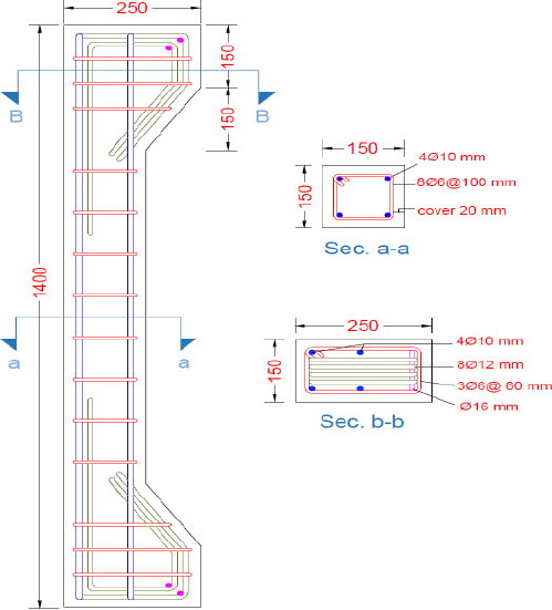
Layout of reinforcement in the tested columns.
|
Group No. |
Specimen Symbol (Ci) |
Fire Exposure (Ti) (°C) |
Fire Duration (Di) (min) |
Repair of Fire Damaged Specimen (R) |
|---|---|---|---|---|
| Control | C1 | - | - | - |
| Group One | C2 T500D60 | 500 | 60 | - |
| C3 T500D60R | 500 | 60 | R | |
| C4 T500D120 | 500 | 120 | - | |
| C5 T500D120R | 500 | 120 | R | |
| Group Two | C6 T700D60 | 700 | 60 | - |
| C7 T700D60R | 700 | 60 | R | |
| C8 T700D120 | 700 | 120 | - | |
| C9 T700D120R | 700 | 120 | R |
It is noteworthy that all eight columns in both groups were subjected to a preloading level equal to 50% of Pu (178.5 kN) during fire exposure, with a fixed load eccentricity of e = 45 mm (e/h = 0.3) for all specimens. Table 3 provides a comprehensive summary of the details for all column groups.
| Group No. |
Specimen Symbol (Ci) |
Ultimate Load Capacity kN | Percentage Decreasing Load Carrying Capacity (%) | Ultimate Axial Deformation (mm) | Ultimate Mid-height Lateral Deflection(mm) |
|---|---|---|---|---|---|
| Control | C1 | 357 | 0 | 10.33 | 10.63 |
| Group One | C2 T500D60 | 276 | -22.68 | 8.8 | 11.24 |
| C3 T500D60R | 382 | +7 | 11.8 | 26.4 | |
| C4 T500D120 | 236 | -33.89 | 8.39 | 11.16 | |
| C5 T500D120R | 359 | +0.56 | 12.33 | 25.12 | |
| Group Two | C6 T700D60 | 207 | -42.02 | 9.31 | 12.23 |
| C7 T700D60R | 338 | -5.32 | 10.8 | 18.36 | |
| C8 T700D120 | 182 | -49.02 | 9.08 | 14.89 | |
| C9 T700D120R | 325 | -8.96 | 11.87 | 22.41 |
4. CASTING PROCEDURES
A central batching mixer with a capacity of 10 m3, provided by Al-Mustaqbal Ready-Mix Concrete Company, was employed to prepare the concrete used in this study. Prior to casting, the interior surfaces of the cube and cylinder molds were thoroughly cleaned and lubricated to prevent adhesion with the hardened concrete. Each steel reinforcement cage for the columns was then placed horizontally within the wooden formwork and securely fixed in position. Concrete was poured in a single layer into each mold, followed by manual compaction and vibration for two minutes using an internal vibrator. The conventional procedures for layer placement and rodding were strictly followed to ensure adequate compaction of the concrete in the cube and cylinder molds, as illustrated in Fig. (2).
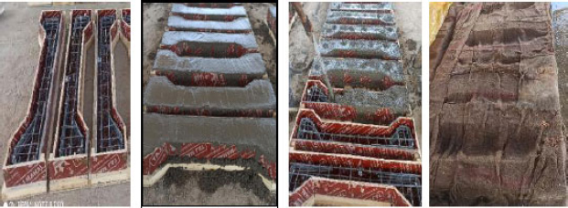
Casting process phases.
5. FIRE TEST
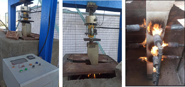
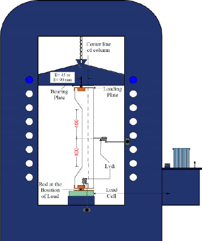
The columns were subjected to fire several months after casting using a brick furnace with internal dimensions of 1400 × 1400 × 1150 mm, as depicted in Fig. (3). Two target temperature levels of approximately 500 °C and 700 °C were adopted in combination with fire exposure durations of 60 and 120 minutes to investigate the combined influence of temperature level and exposure time. Furnace temperature was regulated automatically via a digital controller connected to a gas regulator, which adjusted the fuel supply based on real-time sensor readings to maintain the desired setpoint. Temperature monitoring was conducted using K-type thermocouples with a diameter of 4 mm. To simulate the natural cooling phase following fire exposure, the furnace cover was removed, and the specimens were allowed to cool under ambient conditions. The fire-affected length of each column was approximately 800 mm. The exposed portion of the columns was subjected to heating from all four sides inside the furnace to achieve approximately uniform thermal exposure. The loading corbels and supporting system were positioned outside the primary heating zone to minimize their influence on heat distribution. Thermal insulation was provided near the column ends to limit heat transfer beyond the intended exposure region and to maintain a controlled heating configuration during testing. All columns were tested under eccentric axial loading. Column C1 served as the control specimen and was not exposed to fire. The ultimate axial load capacity (Pu) was experimentally determined from the control column test. Based on this measured value, columns C2 through C9 were preloaded to 178.5 kN, corresponding to approximately 50% of the ultimate axial capacity prior to fire exposure. Comprehensive details of the furnace, testing apparatus, and preloading system are presented in Fig. (4). During the fire tests, the exposure regime was carefully controlled to ensure that the average furnace temperature satisfactorily followed the standard temperature–time relationship specified in ASTM E119-20. The standard fire curve can be expressed as T = 20 + 345 log10(8t + 1), where T is the furnace temperature (°C) and t is the exposure time (min). A comparison between the measured furnace temperatures and the ASTM E119-20 standard curve is presented in Fig. (5), showing good agreement throughout the fire period.
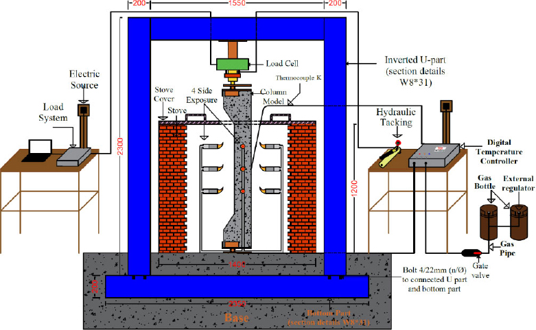
Description of the loading frame.
Specimens subjected to fire exposure under pre-loading curve.
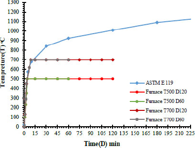
Standard fire exposure according to ASTM E119-20.
6. REPAIR OF FIRE-DAMAGED COLUMN SPECIMENS
The rehabilitation of fire-exposed columns (C3, C5, C7, and C9) was performed through the following key procedures:
(a) Removal of Damaged Concrete: The deteriorated outer concrete layer was carefully removed manually until the longitudinal reinforcement was fully exposed. Mechanical methods were avoided to prevent dynamic vibrations that could compromise the structural integrity of the columns.
(b) Installation of Shear Connectors: 4 mm-diameter shear connectors were installed horizontally on all sides of the stirrups to ensure a reliable bond between the original concrete core and the newly cast normal concrete (NC).
(c) Epoxy Preparation and Application: The epoxy resin (Sikadur®-32 LP) was prepared by stirring the base and hardener separately, then thoroughly mixing them with a slow-speed drill for 2 minutes until a uniform color was obtained. Approximately 90 minutes prior to casting the NC layer, the cleaned surface of the existing concrete was coated with epoxy to enhance adhesion between the old and new concrete layers.
(d) Casting of New Concrete: A new layer of normal concrete (NC) with a compressive strength of 29.4 MPa was cast and subsequently cured for 28 days. All steps are illustrated in Fig. (6).
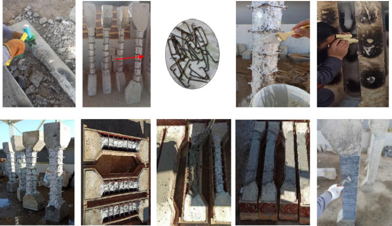
Sequential steps of RC column repair.
For the application of CFRP sheets on the fire-exposed columns, the following procedures were implemented:
(1) CFRP Sheet Cutting: The CFRP sheets were cut to the required lengths, and the concrete surface was thoroughly cleaned to remove any contaminants.
(2) Epoxy Preparation: The two components of the epoxy adhesive (Sikadur-330, types A and B) were mixed in a 4:1 ratio, respectively, until a homogeneous color was obtained.
(3) Epoxy Application: A layer of epoxy approximately 1.5 mm thick was applied to both the column surface and the CFRP sheets.
(4) CFRP Sheet Installation: The CFRP sheets were carefully placed on the epoxy-coated column surface. Pressure was applied with a rubber roller to ensure full contact and expel excess epoxy from both sides of the sheets. Any residual epoxy was removed from the edges of the CFRP sheets, as illustrated in Fig. (6).
Although the rehabilitation procedure in this study was conducted with the columns positioned horizontally to facilitate laboratory implementation and ensure controlled casting conditions, the proposed technique can be practically applied to existing structures under field conditions. In real structures, the removal of damaged concrete cover and its replacement with repair mortar or castable concrete can be performed while the column remains in a vertical position, using conventional repair techniques such as formwork confinement and staged casting. Moreover, partial unloading or temporary structural support can be adopted during rehabilitation to ensure safety and proper bonding. Therefore, the proposed rehabilitation method remains applicable for practical post-fire strengthening of reinforced concrete columns.
7. TEST SETUP AND PROCEDURE
The specimens were tested under monotonic loading using a hydraulic universal testing machine with a maximum capacity of 2500 kN. A load cell installed at the base of the machine was connected to a data logger to continuously record the applied load. The load was gradually increased until specimen failure, while the corresponding load–deflection response was captured. Two linear variable differential transformers (LVDTs) were installed along the height of each eccentric column to monitor axial and lateral displacements. Specifically, two LVDTs were positioned at the base to measure axial shortening at each loading increment, while one LVDT was placed at the mid-height of the column to record lateral deflection. The measurements were repeated at each stage of loading until failure. During the testing, special safety precautions were observed when monitoring crack formation. A detailed assessment of the failure modes, crack patterns, and ultimate load capacities of the columns was performed, as illustrated in Fig. (7).
Test setup with instrumentation details.
8. RESULTS AND DISCUSSION
The experimental outcomes for each column were systematically compared with those of the other specimens to assess the effects of fire exposure duration and temperature intensity, while maintaining consistent preload and load eccentricity. The evaluated parameters encompassed the failure mode, ultimate load capacity, initial cracking load, and axial deformations of the columns. A summary of these results is presented in Table 3.
8.1. Load Carrying Capacity
The load-carrying capacity represents the maximum ultimate load that the tested column specimens can sustain before a noticeable drop in the testing machine readings occurs, accompanied by rapid and irreversible deformation, which signifies structural failure. The results indicated that the fire-exposed columns in the first group exhibited higher residual load capacity than those in the second group, which is a normal and expected outcome due to the lower severity of thermal exposure.
Compared with the unexposed reference column, the ultimate load-carrying capacity of specimens C2T500D60 and C4T500D120 in the first group, which were subjected to 500 °C for 60 and 120 minutes, decreased by 22.68% and 3.89%, respectively. Following this, the fire-damaged columns C3T500D60R and C5T500D120R were retrofitted using a full carbon fiber reinforced polymer (CFRP) wrapping system. The results showed that this strengthening technique effectively restored and slightly enhanced their ultimate capacity, achieving increases of 7% and 0.56%, respectively, compared with the reference column.
When the exposure temperature was raised to 700 °C for 60 and 120 minutes, the second-group specimens C6T700D60 and C8T700D120 exhibited more severe reductions in ultimate capacity (42.02% and 49.02%, respectively) relative to the reference column. After retrofitting using CFRP jacketing, specimens C7T700D60R and C9T700D120R did not show improvements; instead, their ultimate capacity further decreased by 5.32% and 8.96%, respectively, compared with the reference specimen. This slight reduction is attributed to the extensive thermal damage and the destruction of internal concrete bonds caused by higher fire temperatures, as also reported by Cao et al. (2023) [17].
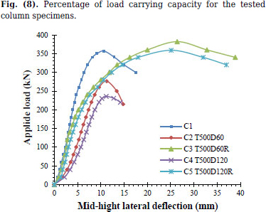
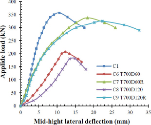
The primary objective of this study is to evaluate the effectiveness of CFRP in enhancing the load-carrying capacity of fire-damaged reinforced concrete columns. Full CFRP confinement significantly improved the performance of specimens exposed to 500 °C, increasing their ultimate load capacity by 38.41% and 52.12% compared with the corresponding fire-damaged columns. For the specimens exposed to 700 °C (C7T700D60R and C9T700D120R), CFRP confinement also improved the load capacity by 63.29% and 78.57% relative to their corresponding fire-damaged specimens, as shown in Fig. (8). However, despite this percentage increase, the rehabilitated columns did not recover the capacity level achieved by specimens exposed to lower temperatures due to severe thermal damage.
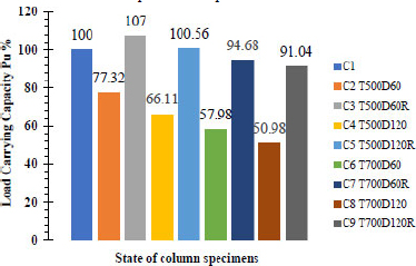
Percentage of load carrying capacity for the tested column specimens.
8.2. Load Displacement Response of Reinforced Concrete Columns
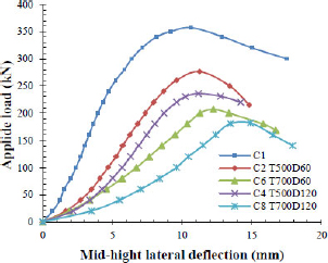
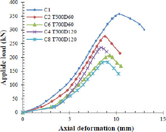
There is a noticeable convergence between the lateral and axial displacement values, both indicating an increase in ultimate displacement as the fire exposure temperature rises. Strengthening with CFRP improved the displacement behavior of the columns under loading. Figs. (9–14) present selected load–displacement curves. The load–deflection responses of the second group exhibited greater sensitivity to elevated temperatures compared to the first group. However, the use of CFRP strengthening for the second group did not result in any measurable enhancement in displacement performance.
Load-deflection of group one's exposed and strengthened column.
Load-deflection of group two's exposed and strengthened column.
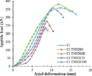
Load –axial deformation of group one's exposed and strengthened column.
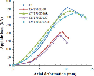
Load –axial deformation of group two's exposed and strengthened colum.
Load –deflection of exposed to 500°C and 700°C.
Load – axial deformation of exposed 500°C and 700°C.
8.3. First Crack Load
The crack width was measured using a crack meter, while the initiation of the first visible crack was identified through direct observation and the corresponding load was recorded. In eccentrically loaded column specimens, transverse flexural cracks typically originate in the tension zone and propagate toward the compression zone, whereas longitudinal cracks generally initiate near the corbel region as shear cracks. Very fine microcracks, commonly referred to as hairline cracks, were observed in the fire-exposed specimens, indicating that thermal effects had already induced preliminary cracking prior to mechanical testing. The black-colored cracks resulted from the influence of eccentric loading during mechanical testing, while the red-colored cracks were attributed to axial loading effects following fire exposure. Based on Table 4, it is evident that the non-fire-exposed reference columns exhibited the smallest crack widths among all specimens, with an average value of 0.24 mm, as illustrated in Fig. (15a). In contrast, the fire-exposed columns exhibited larger average crack widths of 0.36 and 0.74 mm, as shown in Fig. (15b). This increase is primarily attributed to the detrimental effects of elevated temperatures on the concrete microstructure.
| Group No. |
Specimen Symbol (Ci) |
Maximum Crack Width After Exposure to fire (mm) | Crack Width at Service Load (mm) | Location of The Crack |
|---|---|---|---|---|
| Control | C1 | - | 0.24 | In the middle of the column |
| Group One | C2 T500D60 | 0.2 | 0.36 | In the last quarter of the column |
| C3 T500D60R | 0.22 | - | In the middle of the column | |
| C4 T500D120 | 0.36 | 0.42 | In the last quarter of the column | |
| C5 T500D120R | 0.38 | - | In the first quarter of the column | |
| Group Two | C6 T700D60 | 0.46 | 0.48 | In the middle of the column |
| C7 T700D60R | 0.48 | - | In the last quarter of the column | |
| C8 T700D120 | 0.62 | 0.74 | In the first quarter of the column | |
| C9 T700D120R | 0.58 | - | In the middle of the column |
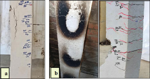
Spread of crack in specimens, a. Column specimens without fire, and b. Column specimens with fire exposure.
9. FAILURE’S MODE
In general, the columns were tested under an eccentric load of 45 mm. Columns subjected to this type of loading typically exhibited compression-controlled failure. The failure process initiated gradually with the appearance of cracks on the tension side, followed by their progressive propagation toward the compression zone and across the remaining faces of the column. For the unexposed control column, crack initiation and propagation were relatively slow and limited compared with the fire-exposed specimens. In contrast, the fire-exposed columns contained pre-existing cracks caused by thermal degradation, which accelerated crack propagation and widening under lower load levels, as illustrated in Fig. (15). Moreover, the ease of crack initiation increased with longer fire exposure durations; specimens exposed for 120 minutes exhibited wider and more numerous cracks than those exposed for 60 minutes at the same temperature. Failure generally occurred through spalling of the concrete cover in the compression zone within the middle third of the column. The cover then began to crush at the mid-height and subsequently developed into longitudinal and transverse cracking until the entire concrete cover was detached, as shown in Figs. (15 and 16).
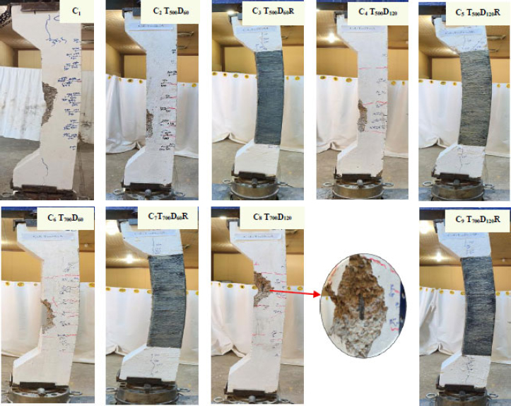
Failure modes of columns after testing.
For the columns strengthened with carbon fiber–reinforced polymer (CFRP), failure was characterized by tearing of the CFRP sheet on the tension side and spalling on the compression side, accompanied by significant buckling of the column, as presented in Fig. (17). This behavior confirms that fire-damaged, CFRP-strengthened columns exhibit a failure pattern similar to that of unstrengthened columns. The CFRP confinement contributed to restraining the concrete core, thereby increasing resistance to crushing under the same load level. Furthermore, the applied load was shared between the reinforced concrete column and the CFRP composite layer. The CFRP sheets possess very low axial compressive stiffness due to their small thickness compared with the concrete section, which caused rupture of the epoxy matrix. Consequently, the primary load-carrying component within the composite layer was the unidirectional CFRP fibers, which are incapable of carrying axial compressive forces. Thus, the CFRP contribution to resisting axial compression was limited to the epoxy layer-an amount considered negligible. Accordingly, when a CFRP-confined concrete column is subjected to axial loading, the CFRP jacket primarily resists hoop tensile stresses, while the concrete core undergoes triaxial compression (Khalaf et al. 2025) [22].
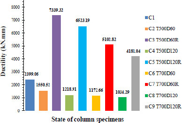
The ductility of specimens.
10. DUCTILITY
In this study, the method of energy absorption capacity was adopted to evaluate the ductility of reinforced concrete columns. The energy absorption capacity of a concrete column is defined as the area under the load–displacement curve up to the maximum load. The calculated areas under the curves, representing the columns’ ductility, are presented in Fig. (17).
The results clearly indicate that strengthening with carbon fiber–reinforced polymer (CFRP) significantly enhances the ductility of fire-exposed columns. Specifically, CFRP strengthening increased ductility by 188.92% for columns exposed to 500 °C and 93.49% for those exposed to 700 °C. These findings demonstrate the effectiveness of CFRP in improving the post-fire ductile behavior of reinforced concrete columns, thereby increasing their energy absorption capacity and resistance to sudden failure. These results are consistent with the findings of Gao et al. (2025) [19], who reported that confining concrete with FRP sheets can substantially enhance the concrete’s strength, ductility, and energy absorption capacity.
11. STIFFNESS PARAMETER
In structural mechanics, stiffness is defined as the amount of load required to produce a unit deformation in a structural member. One commonly used approach to evaluate stiffness is the secant slope method, in which the slope of the line drawn on the load–deflection curve at 75% of the ultimate load is taken as the stiffness value [23]. As illustrated in Fig. (18), the stiffness of each column was calculated and subsequently compared with that of the control specimen. The results clearly show that stiffness decreases significantly with increasing temperature and exposure duration following fire damage. The greatest reduction was observed at an exposure temperature of 700 °C, where stiffness dropped by 75.39%, accompanied by a notable reduction in load-carrying capacity.
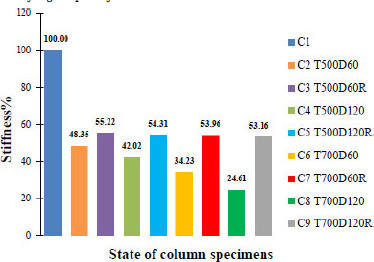
Stiffness of specimens.
Conversely, strengthening with CFRP did not provide any improvement in stiffness. In fact, for columns exposed to 500 °C, the stiffness decreased by 45.23% after CFRP strengthening. Similarly, columns exposed to 700 °C experienced a reduction in stiffness of 46.44%. This behavior can be attributed to the inherent characteristics of unidirectional CFRP fibers. While CFRP exhibits excellent tensile resistance, it possesses negligible axial compressive capacity, particularly when applied as thin external sheets. Early-stage axial stiffness is governed primarily by the concrete core and the steel reinforcement, rather than by the external CFRP jacket. Consequently, CFRP confinement is effective in enhancing strength and ductility at later stages of loading, but it does not contribute meaningfully to improving the initial stiffness of fire-damaged columns.
CONCLUSION
Based on the experimental results, several key conclusions can be drawn regarding the behavior of the studied columns. After fire exposure, the specimens in Group One exhibited higher stiffness compared to those in Group Two, as indicated by the load-carrying capacity tests. This behavior is attributed to the higher fire temperatures, which caused greater thermal expansion in both the concrete and reinforcement, leading to the development of internal stresses.
Increasing the duration of fire exposure significantly reduced the load-carrying capacity of the columns. For Group One, the capacity decreased by 22.68% and 33.89% after exposure to 500 °C for 60 and 120 minutes, respectively, compared with the reference column. Meanwhile, Group Two, exposed to 700 °C, experienced larger reductions of 42.02% and 49.02% for the same exposure periods.
Observations of the crack patterns revealed that crack widening and propagation became more pronounced with higher fire temperatures and longer exposure durations, as evidenced by monitoring the behavior of preloaded and fire-exposed columns.
The CFRP-strengthened specimens in Group One successfully regained their original load-carrying capacity, whereas those in Group Two were unable to recover their initial capacity due to the substantial reduction in structural resistance after fire exposure.
Applying full CFRP wrapping to the fire-damaged columns resulted in a notable improvement in performance. Load-carrying capacity increased by 38.41–78.57% relative to the fire-exposed specimens, and ductility improved by 93.49–188.92% compared with the burned columns. However, CFRP strengthening did not yield any enhancement in column stiffness.
The findings of this study are subject to certain limitations. The experimental program was conducted on laboratory-scale reinforced concrete columns under controlled fire exposure conditions, which may not fully reflect the complex behavior of full-scale structural elements in real fire scenarios. In addition, the study considered a limited range of fire exposure temperatures, durations, and a single level of sustained eccentric axial loading, while other influential parameters such as load ratio, eccentricity magnitude, column slenderness, and reinforcement detailing were not investigated. The rehabilitation approach was restricted to replacing the damaged concrete cover with normal concrete and strengthening using CFRP sheets, whereas alternative repair materials and strengthening techniques were not examined. Furthermore, long-term performance aspects of the rehabilitated columns, including durability and behavior under repeated fire exposure, were beyond the scope of this study.
AUTHORS’ CONTRIBUTIONS
The authors confirm contribution to the paper as follows: M.M., S.A.and A.M.: Conceptualization; M.M.: Data curation; A.M.: Formal analysis; M.M.: Investigation; S.A.: Methodology; S.A.and A.M.: Project administration; A.M.: Resources; M.M.: Software; S.A.and A.M.: Supervision; M.M., S.A.and A.M.: Validation; S.A.: Visualization; S.A.: Writing-original draft preparation; A.M.: writing-review and editing. All authors have read and agreed to the published version of the manuscript.
LIST OF ABBREVIATIONS
| RC | = Reinforced Concrete |
| CFRP | = Carbon Fiber Reinforced Polymer |
| NC | = Normal Concrete |
| FRP | = Fiber Reinforced Polymer |
| Pu | = Ultimate Axial Load Capacity |
| NSC | = Normal-strength Concrete |
| C1 | = Control Column |
| CFRP | = Carbon Fiber Reinforced Polymer |
AVAILABILITY OF DATA AND MATERIAL
The data supporting the findings of this article are available from the corresponding author [M.M], upon reasonable request.
ACKNOWLEDGEMENTS
Declared none.