All published articles of this journal are available on ScienceDirect.

Experimental and Numerical Investigation of Tapered Steel Girders with Flat and Sinusoidal Webs under Three-point Loading
 iD
Wael Shawky Abdulsahib1
iD
iD
Wael Shawky Abdulsahib1
iD
Authors Info & Affiliations
Abstract
Introduction
Tapered steel I-girders with sinusoidal corrugated webs offer a promising alternative to conventional flat-web designs, yet no experimental study has addressed tapered configurations.
Methods
To address this gap, six tapered girders - three with flat webs and three with sinusoidal corrugated webs - were tested under three-point loading at mid-span depths of 400, 600, and 800 mm, combining experimental work with nonlinear finite element modelling.
Results
The corrugated-web specimens carried 50%, 43%, and 13% more load than their flat-web counterparts at increasing depths. Larger strength gains at the shallower sections point to a pronounced dependence on the corrugation-to-depth ratio. The failure mechanisms were markedly different as well. Finite element models developed in ABAQUS captured the experimental ultimate loads and mid-span deflections well, with mean discrepancies of roughly 3% and 3.3%, respectively.
Discussion
Comparison with available analytical predictions showed that the Nikoomanesh–Goudarzi formula gave reasonable estimates for the shallower specimens but overestimated capacity by 10% at 800 mm depth, while EN 1993-1-5 remained conservative for all specimens, with Pexp/PEN ratios between 1.80 and 2.05, suggesting that dedicated provisions for such members are needed.
Conclusion
Taken together, the findings indicate that sinusoidal corrugated webs can meaningfully improve both shear resistance and post-buckling ductility in tapered girders - especially when the corrugation-to-depth ratio exceeds about 15%. It is worth noting that neither AISC 360 nor EN 1993-1-5 currently covers this configuration. The tension field mechanisms observed here suggest that extending both codes to cover corrugated-web tapered members is justified, and the present dataset serves as the first experimental benchmark for such an extension.
1. INTRODUCTION
Tapered steel I-girders, in which web depth varies along the span to conform to the bending moment and shear demand, are widely used in bridge and building construction, providing significant structural efficiency and material economy. Due to this change in depth, non-uniform stress fields are produced which alter both local and global buckling behaviour in ways that can differ substantially from prismatic members [1, 2].
Corrugated steel webs have substantial out-of-plane stiffness, which plays a key role in developing post-buckling tension field action, improving shear resistance without increasing self-weight. These advantages have drawn considerable interest as a means of improving shear resistance without increasing self-weight [3, 4]. Prismatic girders with trapezoidal corrugations are well studied in the literature, but sinusoidal corrugated webs in tapered configurations remain largely unexplored. The present study seeks to address this gap.
In earlier work, the present authors examined tapered girders with trapezoidal corrugated webs under three-point loading conditions [5], establishing valuable data for girders with trapezoidal corrugated profiles. The current study extends that work to sinusoidal corrugated webs, which have a continuous curvature of the sinusoidal profile that influences stress redistribution and post-buckling response. Because both studies share the same experimental girder framework dimensions, a direct comparison of sinusoidal and trapezoidal web performance is reliable; this comparison is presented in Section 3.5.
The available studies on sinusoidal corrugated webs are limited and include parametric studies on web geometry and shear capacity [6], shear buckling analysis [7], girders with web openings [8], and stainless steel variants [9, 10]. Pimenta et al. [11] developed reliability-based design recommendations for composite sinusoidal-web beams and indicated that the corrugated web contributes negligibly to flexural capacity due to the accordion effect, but it substantially enhances shear resistance and local buckling performance. Nikoomanesh and Goudarzi [12] proposed an interactive shear buckling formula that takes into consideration the effects of local buckling, global buckling, and yielding criteria for prismatic sinusoidal corrugated-web girders through experiments and finite element modelling. Both studies found that sinusoidal webs, distinct from trapezoidal profiles, exhibit elasto-plastic buckling behaviour and initiate local buckling across the region between consecutive wave peaks. Crucially, though, both were confined to prismatic girders. Zhou et al. [13] investigated tapered and prismatic corrugated-web girders and concluded fundamentally different shear response patterns. Likewise, the available analytical models developed for prismatic corrugated webs that account for axial–bending interactions and shear stress distributions [14] cannot be applied directly to tapered geometries.
In another study, the so-called “accordion effect” identified by Huang et al. [15] for trapezoidal corrugated webs manifests quite differently in sinusoidal profiles, calling for dedicated experimental and numerical work.
To the authors' knowledge, no prior experimental study has examined the shear behaviour and failure modes of tapered steel I-girders with sinusoidal corrugated webs - specifically considering the combination of linearly varying web depth with a sinusoidal corrugation profile.
Due to the advantages of corrugated webs in prismatic configurations, sinusoidal corrugation is expected to improve shear resistance and web buckling resistance relative to flat-web girders, with the magnitude of improvement depending on the corrugation-to-depth ratio. In light of these gaps, the present study aims to: (1) experimentally compare the ultimate load capacity, load–deflection response, failure modes, and web strain distribution of tapered I-girders with sinusoidal corrugated webs against flat-web counterparts at three mid-span web depths (400, 600, and 800 mm); and (2) develop and validate nonlinear finite element models in ABAQUS capable of reproducing the observed load-carrying capacity, deformation characteristics, and stress distribution patterns. The findings are intended to provide the first experimental benchmarks for tapered sinusoidal-web girders, to quantify the influence of the corrugation-to-depth ratio on structural performance, and to assess the suitability of sinusoidal corrugated webs as a practical alternative to conventional flat-web configurations in tapered steel girders. The chosen girder dimensions and loading configuration are applicable to short- to medium-span roof beams and to footbridge girders, where the use of tapered steel members offers material savings.
2. EXPERIMENTAL PROGRAM
2.1. Specimen Details and Configurations
Six tapered steel I-girders were fabricated and tested. The specimens were categorised into two groups: three flat-web girders named TFW400, TFW600, and TFW800, and three sinusoidal corrugated-web girders (TSW400, TSW600, and TSW800), where the numerical suffix indicates the mid-span web depth in millimetres. Dimensional properties such as flange width and thickness, and total length (1800 mm), were kept identical to allow a controlled comparison. The three mid-span depths of 400, 600, and 800 mm were selected, representing a practical range of tapered girder proportions encountered in short- to medium-span bridges and various building applications.
The web depth varied linearly from each support toward mid-span, establishing the tapered geometry. End web depths (hw1) were 200 mm, 400 mm, and 600 mm, with corresponding mid-span web depths (hw2) of 400 mm, 600 mm, and 800 mm, respectively. All web plates had a uniform thickness of 2 mm. Because the web profile is sinusoidal, its arc length exceeds the flat web projected length, resulting in a marginally higher web steel weight than the flat webs; however, the flange plates, stiffeners, and girder length were identical for all six specimens. Fabrication was carried out by a single workshop using the same welding procedure and quality control process for all specimens. Stiffeners were positioned at the ends and at mid-span to prevent premature web buckling at the load and support locations.
For the sinusoidal corrugated-web specimens, the web plates were cold-formed into a sinusoidal profile prior to welding. The corrugation geometry was characterised by a corrugation depth of 71 mm and a wavelength of 341 mm, as illustrated in Fig. (1). These dimensions were adopted from the previous study [5], maintaining consistency with the experimental programme. Flange plates were 10 mm thick, and bearing stiffeners were fabricated from 15 mm-thick plates. All flange and stiffener dimensions were identical across all six specimens.
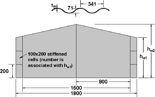
Corrugation geometry and dimensional notations of the tested girders.
2.2. Material Properties
The mechanical properties of the steel plates used in the fabrication of the test specimens were determined through uniaxial tensile coupon tests conducted in accordance with ASTM E8/E8M-22. Coupons were extracted from the same steel plates used to fabricate the girder components to ensure representative material characterisation. A minimum of three coupons were tested for each plate thickness.
Two distinct steel grades were used in the specimen fabrication. The flange plates and bearing stiffeners were cut from 10 mm and 15 mm-thick mild steel plates, while the web plates were fabricated from 2 mm-thick steel sheets. The measured mechanical properties obtained from the coupon tests are summarised in Table 1.
| Component | Plate Thickness (mm) | Yield Strength, fy (MPa) | Ultimate Strength, fu (MPa) | Elastic Modulus, E (GPa) | Elongation at Fracture (%) |
|---|---|---|---|---|---|
| Flanges and stiffeners | 10, 15 | 391 | 486 | 200 | 8 |
| Web plates (flat and sinusoidal corrugated) | 2.0 | 425 | 518 | 200 | 7 |
The yield strength was determined using the 0.2% offset method. The elastic modulus was 200 GPa. The measured yield strengths across the three coupons for each plate thickness varied by no more than 5%, which is sufficient to support the comparison between flat-web and sinusoidal-web girders.
It should be noted that the sinusoidal corrugated web plates were cold-formed into shape prior to welding. The coupon tests were performed on flat plate samples prior to cold forming; consequently, any potential increase in yield strength or reduction in ductility resulting from the cold-forming process was not explicitly captured in the reported material properties.
2.3. Test Setup and Instrumentation
A three-point bending configuration was employed for all tests. Mid-span loads were applied using a hydraulic actuator acting through a steel spreader plate to ensure uniform load introduction, as illustrated in Fig. (2). Pin and roller supports were positioned 100 mm from each end of the girder, creating a clear span of 1600 mm between support centrelines.
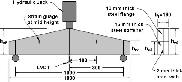
Typical test setup and positions of strain gages [first published in Asian Journal of Civil Engineering, vol. 26, pp. 2837–2851, 2025, Springer Nature].
Electrical resistance strain gauges were installed at mid-span on both sides of the web to monitor in-plane strain development throughout loading. Gauge locations are indicated in Fig. (2). Gauges were bonded at the flat nodal regions between corrugation peaks to obtain better adhesion and to improve the capture of in-plane shear strains away from local stress concentrations at the corrugation folds. Mid-span vertical deflections were continuously recorded using a Linear Variable Differential Transformer (LVDT) positioned at the underside of the bottom flange at mid-span. Load, strain, and deflection data were acquired simultaneously using a digital data acquisition system at a sampling rate sufficient to capture the full pre- and post-buckling response.
3. EXPERIMENTAL RESULTS AND DISCUSSION
3.1. Ultimate Load Capacity
The ultimate load capacities are summarized in Table 2. The shear span-to-depth ratios for the 400, 600, and 800 mm specimens were 2.0, 1.33, and 1.0, respectively, confirming that all specimens are within a shear-dominated regime. For flat-web girders, increasing the mid-span depth from 400 to 600 mm and then to 800 mm raised load capacity by 60% and 43%, respectively. Sinusoidal-web girders followed a similar trend, with increases of 53% (TSW400 to TSW600) and 13% (TSW600 to TSW800). Across all configurations, sinusoidal-web girders consistently outperformed their flat-web counterparts, with load capacity improvements of 50%, 43%, and 13% for the 400, 600, and 800 mm specimens, respectively.
| Specimens | Ultimate Load (kN) | Flat Web Girders Load Capacity Improvement (%) | Sinusoidal Web Girders Load Capacity Improvement (%) | Improvement of Sinusoidal over Flat Web (%) |
|---|---|---|---|---|
| TFW400 | 270 | --- | --- | --- |
| TFW600 | 433 | 60 | --- | --- |
| TFW800 | 620 | 43 | --- | --- |
| TSW400 | 405 | --- | --- | 50 |
| TSW600 | 620 | --- | 53 | 43 |
| TSW800 | 703 | --- | 13 | 13 |
The superior performance of sinusoidal-web girders is attributed to their enhanced out-of-plane stiffness and post-buckling resilience. The unique geometry of the web plays a vital role in delaying shear buckling through consistent redistribution of stresses across multiple folds and stabilising tension field action across the web, leading to 50% and 43% load capacity gains at 400 and 600 mm depths. This trend is limited, as for 800 mm, the improvement dropped to 13%, reflecting a strong dependence on geometric proportionality.
This reduced effectiveness at 800 mm can be traced to two interrelated factors:
Geometric limitations: Since the corrugation dimensions are fixed across all specimens, their relative contribution decreases as the web height increases. At 800 mm, the corrugation depth represents only approximately 9% of the total web height, while it is 18% at 400 mm, reducing the web's resistance to out-of-plane deformations.
Global buckling dominance: While sinusoidal corrugations are effective at delaying local buckling, the taller web is more prone to global buckling due to increased slenderness.
3.2. Load–deflection Behavior
All specimens showed linear load–deflection behaviour up to approximately 75–90% of the ultimate load, after which they exhibited nonlinear behaviour associated with web buckling and post-buckling stages. The load–deflection curves for sinusoidal-web and flat-web girders are shown in Figs. (3 and 4), respectively, with an overall representation in Fig. (5).
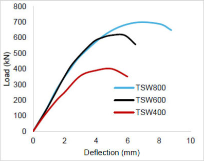
Load– vertical deflection curves for sinusoidal web girders.
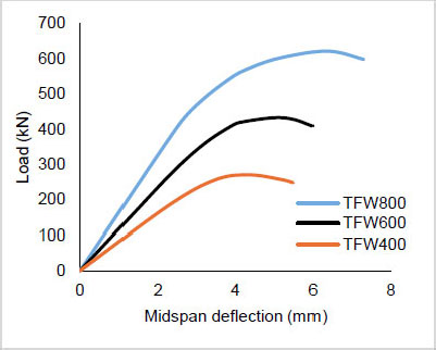
Load– vertical deflection curves for flat web girders.
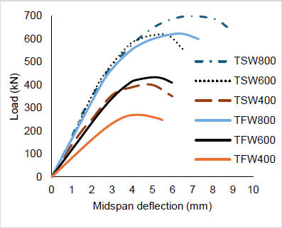
Load– vertical deflection curves for tapered sinusoidal and flat web girders.
Maximum mid-span deflections at failure are summarised in Table 3. As discussed earlier, deeper webs produced larger deflections in both groups, and sinusoidal-web girders reached slightly higher deflections than their flat-web counterparts, reflecting a gain in ductility.
| Specimen | Vertical Deflection (mm) | Increase Relative to Same Web Type (%) | Increase Relative to Flat Web Counterpart (%) |
|---|---|---|---|
| TFW400 | 5.50 | - | - |
| TFW600 | 5.98 | 9 | - |
| TFW800 | 7.28 | 22 | - |
| TSW400 | 6.00 | - | 9 |
| TSW600 | 6.51 | 8 | 9 |
| TSW800 | 8.78 | 35 | 21 |
This enhanced ductility can be evaluated by the amount of energy absorption, which can be calculated by integrating the area under each load–deflection curve up to the maximum recorded deflection using the trapezoidal rule. TSW800 showed approximately 1.4 times the absorbed energy of TFW800 (4.4 kN·m versus 3.15 kN·m). This confirms the observation of more stable tension field action in sinusoidal webs, which sustains load-carrying capacity over a larger deformation range, in contrast to localised shear buckling.
3.3. Failure Modes and Buckling Patterns
All three sinusoidal-web girders developed distributed buckling involving multiple corrugation folds. TSW400 (Fig. 6) showed an interactive mode combining localised web deformation with elements of global instability in which buckling spread across adjacent corrugation panels.
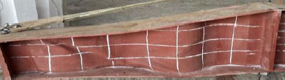
Buckling pattern observed in TSW400 under 3-point loading.
The behaviour of the flat-web girders was quite different. TFW400 (Fig. 7) developed a localised diagonal shear buckle running from the upper flange near the support toward the bottom flange at mid-span. It also exhibited post-buckling strength via a tension field anchored by the flanges and stiffeners [16].
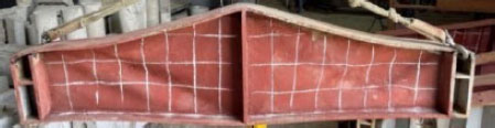
Buckling pattern observed in TFW400 under 3-point loading [first published in Asian Journal of Civil Engineering, vol. 26, pp. 2837–2851, 2025, Springer Nature].
TSW600 (Fig. 8) failed through global buckling, with out-of-plane deformations propagating over consecutive folds.
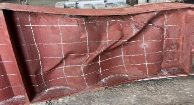
Buckling pattern observed in TSW600 under 3-point loading.
TFW600 (Fig. 9) showed shear buckling across two adjacent web panels, diagonally buckled in both panels, forming a multi-panel shear failure mode.
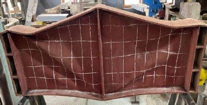
Buckling pattern observed in TFW600 under 3-point loading [first published in Asian Journal of Civil Engineering, vol. 26, pp. 2837–2851, 2025, Springer Nature].
TSW800 (Fig. 10) also failed through global buckling, with out-of-plane deformations propagating over consecutive folds. The web engages significantly in shear resistance through membrane action. Once global buckling initiated in the web, it transitioned to load-carrying through this mechanism, consistent with the tension field mechanism described by Gremza and Basinski [17].
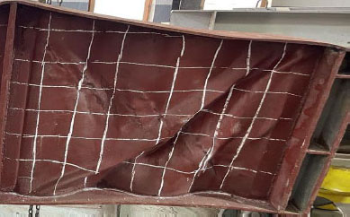
Buckling pattern observed in TSW800 under 3-point loading.
TFW800 (Fig. 11) also failed through diagonal shear buckling and exhibited more extensive plastic deformation, explained by shear hinge development at an advanced load stage [18].
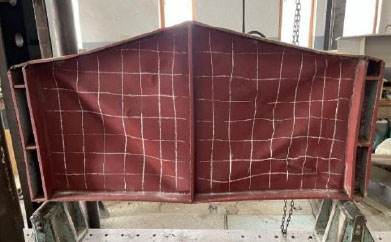
Buckling pattern observed in TFW800 under 3-point loading.
The difference in behaviour between the two web types illustrates the role of the out-of-plane geometry in promoting global stability, delaying failure, and enabling a more ductile post-buckling response. The visual classification of buckling modes is further supported by the web strain distributions presented in Section 3.4 and the FEA results; both support the observed buckling patterns across the six specimens.
3.4. Web Strain Distribution
The strain behaviour of all specimens was monitored by recording the strain from the mid-span strain gauge throughout each test. Load–strain relationships for sinusoidal-web and flat-web girders are presented in Figs. (12 and 13), respectively, with a direct comparison in Fig. (14).
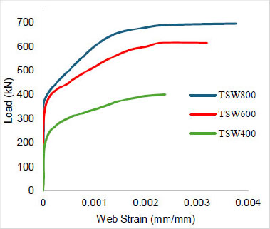
Load-web strain curves for sinusoidal web girders.
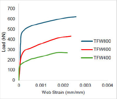
Load-web strain curves for flat web girders.
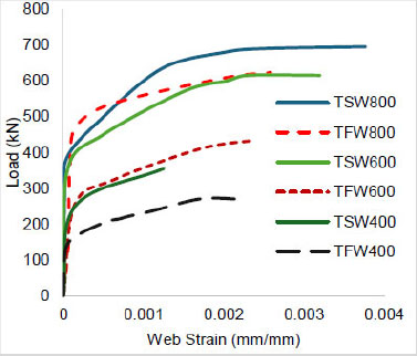
Load-web strain curves for comparison for tapered sinusoidal and flat web girders.
In all specimens, strain varied linearly with load initially, then transitioned to nonlinear behaviour as web buckling developed. This pattern is aligned with observations by Elgaaly and Seshadri [19], who reported nonlinearities associated with local buckling in corrugated webs.
Maximum strains recorded at mid-span are summarised in Table 4. The ultimate strains recorded for the sinusoidal-web girders were higher than their flat-web counterparts across all configurations, with increases of approximately 9%, 36%, and 46% for TSW400, TSW600, and TSW800 relative to TFW400, TFW600, and TFW800, respectively.
| Specimen | Maximum Strain at the Web Mid-span (mm/mm) | Increase Relative to Flat Web (%) |
|---|---|---|
| TFW400 | 0.00219 | --- |
| TFW600 | 0.00235 | --- |
| TFW800 | 0.00258 | --- |
| TSW400 | 0.00238 | 9% |
| TSW600 | 0.00320 | 36% |
| TSW800 | 0.00377 | 46% |
3.5. Comparison with Trapezoidal Corrugated Web Girders
Since both the present study and the authors' earlier work [5] used the same specimen geometries (except for the corrugation type), material properties, fabrication procedures, and testing configurations, a direct comparison of sinusoidal and trapezoidal web performance is possible. Ultimate load capacities for all three web types are summarized in Table 5.
| Specimen Depth (mm) | Flat Web (kN) | Trapezoidal Web (kN) [5] | Sinusoidal Web (kN) | Improvement: Trap. over Flat (%) | Improvement: Sin. over Flat (%) |
|---|---|---|---|---|---|
| 400 | 270 | 486 | 405 | 80 | 50 |
| 600 | 433 | 676 | 620 | 56 | 43 |
| 800 | 620 | 817 | 703 | 32 | 13 |
At 400 mm depth, the trapezoidal web girder showed a higher ultimate load (486 kN), achieving 80% improvement over the flat web. While the 400 mm depth sinusoidal web girder showed (405 kN), achieving 50% improvement over its flat-web girder counterpart. At 600 mm, the gap narrowed (676 kN versus 620 kN, corresponding to 56% and 43% improvements over flat web, respectively). At 800 mm, the trapezoidal profile again achieved more improvement (817 kN versus 703 kN).
The higher performance of the trapezoidal profile, especially at shallower depths, is explained by its longer flat fold lengths, which provide more effective anchorage zones for the diagonal tension field. The discrete web panel geometries formed by the inclined folds confine buckling waves and facilitate load transfer between adjacent folds. On the other hand, the sinusoidal profile, without the flat panels, distributes the out-of-plane deformations more gradually, which benefits ductility but limits the peak shear capacity achievable through tension field action.
That said, the sinusoidal profile offers advantages not reflected in static load comparisons. Its continuous curvature eliminates the fold-corner stress concentrations inherent to trapezoidal profiles, which are known to be susceptible to fatigue crack initiation under cyclic loading [17]. Sinusoidal profiles may also be better suited to automated roll-forming fabrication. The choice between the two profiles in tapered girders therefore involves a trade-off between static shear capacity and potential fatigue performance, a topic that warrants dedicated investigation under cyclic loading conditions.
3.6. Comparison with Analytical Shear Buckling Predictions
The experimental ultimate shear forces of the sinusoidal-web girders were compared with predictions from available analytical models to assess the extent of post-buckling reserve strength. The interactive shear buckling formula proposed by Nikoomanesh and Goudarzi [12] for prismatic sinusoidal corrugated webs was adopted, which combines local buckling, global buckling, and shear yielding - the three standard failure categories for corrugated web beams [7] - through the following interaction expression in Eq. (1):

where τN is the interactive shear capacity stress. The individual terms are defined as below in Eqs. (2 through 4):

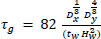

In the above expressions, τl and τg represent the local and global elastic shear buckling stresses, respectively, and τy is the shear yield stress. The equivalent flat panel width b for sinusoidal webs is defined as
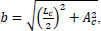 , where Lc and Ac are the corrugation wavelength and the peak-to-peak corrugation depth, respectively. The bending rigidities per unit length parallel and perpendicular to the corrugation direction are given by
 and
and
 where S is the arc length of one sinusoidal wave, and Iy is the second moment of area of one corrugation wave about its neutral axis.
For the tested corrugation geometry, the arc length of one sinusoidal wave was S = 375 mm, and the equivalent panel width was b = 174 mm (calculated as Ac = 71 mm, Lc = 341 mm). Both the local and global buckling stresses exceeded the shear yield stress τy = 245 MPa, confirming that buckling was not a governing mode for the tested corrugation geometry. The interactive shear stress therefore reduced to τN ≈ τy = 245 MPa, indicating that the prismatic formula predicts shear yielding as the controlling failure mode. The corresponding predicted loads are shown in Table 6.
The shear resistance provisions of EN 1993-1-5 [20] were also evaluated. For sinusoidal corrugated webs, the local critical shear stress is given by Eq. (5) below:

and the global critical shear stress is given by Eq. (6) below:
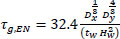
The design shear resistance is obtained from Eq. (7) by applying reduction factors for slenderness to the shear yield capacity:
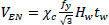
where χc is the minimum of the local and global reduction factors
 and
and
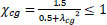 , the local slenderness (λcl) and global slenderness (λcg) parameters can be determined from Eqs. (8 and 9), respectively

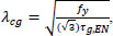
Since no analytical shear buckling formulation currently exists for tapered corrugated-web girders, the mid-span web depth was adopted as the representative section depth Hw in all calculations, providing a direct assessment of whether prismatic models can be applied to tapered configurations. It is acknowledged that the critical shear section in a tapered girder under three-point loading is located near the supports, resulting in the mid-span depth representing an upper-bound estimate of shear capacity, which partly explains the conservative Pexp/PN ratios observed for the 400 and 600 mm specimens.
For the 400 mm and 600 mm specimens, the experimental ultimate loads are in agreement with the interactive buckling predictions [12], with Pexp/PN ratios of 1.03 and 1.05, respectively. This indicates that the prismatic formula provides a close estimate at these depths. However, for the 800 mm specimen, the formula overestimates the experimental capacity by 10%. This divergence arises because the Nikoomanesh–Goudarzi [12] formula was developed for prismatic girders. This is aligned with the failure modes described in Section 3.3, where TSW400 and TSW600 exhibited distributed buckling across multiple corrugation folds only after the web had reached its shear yield capacity, indicating that the observed buckling was elasto-plastic rather than an elastic instability. In a tapered configuration, the varying section depth introduces additional instability mechanisms - particularly the transition from local to global buckling at larger web heights - that the prismatic formulation does not capture. Specifically, three assumptions of the prismatic formulation break down under tapering: the assumption of uniform section depth along the entire shear span, the assumption of uniform shear stress distribution across the entire web height, and the assumption that corrugation geometry results in consistent tension field anchorage throughout the entire member length. At 800 mm depth, where the corrugation depth is only 9% of the web height, the corrugation geometry can no longer anchor effective tension fields across the full web height, and the measured capacity falls below the shear yield limit predicted by the prismatic model. This provides direct evidence that prismatic analytical models cannot be unconditionally extended to tapered sinusoidal-web girders, and that the corrugation-to-depth ratio is a critical parameter governing the applicability of existing formulations.
The EN 1993-1-5 provisions, by contrast, remained conservative across all three configurations, with Pexp/PEN ratios ranging from 1.80 to 2.05, confirming significant conservatism that suggests dedicated design provisions for tapered sinusoidal-web girders are warranted.
The results suggest that a taper correction factor may be introduced into the interactive shear buckling formula to extend its applicability to tapered configurations, and its development is recommended as a direction for future research.
4. FINITE ELEMENT MODELING
Three-dimensional finite element models of all six tapered girder specimens were developed using the commercial software ABAQUS/Standard to simulate the structural response under static three-point loading. The models were constructed to replicate the laboratory conditions as closely as possible, including specimen geometry, material behaviour, loading arrangement, and boundary conditions. Both geometric and material nonlinearities were incorporated to capture the full load–deflection response through the elastic, buckling, and post-buckling stages.
4.1. Model Geometry and Mesh
The girder geometry - including flanges, web plates, and bearing stiffeners - was modelled using the measured dimensions of each test specimen. For the sinusoidal-web girders, the corrugated web profile was generated by defining the sinusoidal wave geometry with a corrugation depth of 71 mm and a wavelength of 341 mm, consistent with the fabricated specimens (Fig. 1). All components were modelled as shell elements positioned at the mid-surface of each plate.
The models were discretised using four-node doubly curved shell elements with reduced integration and hourglass control (S4R), which are well suited for thin-walled structures exhibiting both membrane and bending behaviour. The S4R element formulation efficiently captures large deformations and local buckling phenomena while maintaining computational economy through the single-point integration scheme, with hourglass stabilisation preventing spurious zero-energy modes.
Five integration points were used through the shell thickness to adequately capture through-thickness stress variation during bending and buckling.
A mesh convergence study was performed to determine the optimal element size, balancing accuracy and computational cost. Three mesh densities were evaluated for the TFW600 specimen: a coarse mesh with an element size of approximately 53 mm, a medium mesh with 40 mm, and a fine mesh with 30 mm. The ultimate load predictions were 398 kN, 412 kN, and 414 kN for the coarse, medium, and fine meshes, respectively, indicating convergence within 0.5% between the medium and fine discretisations.
A comparable convergence study was conducted for the TSW600 sinusoidal-web specimen, which confirmed that a global element size of 40 mm yielded converged results for the corrugated web geometry as well. Based on these studies, a global element size of approximately 40 mm was adopted for all subsequent models.
The finite element mesh configurations for representative flat-web and sinusoidal-web girder models are shown in Figs. (15 and 16), respectively.
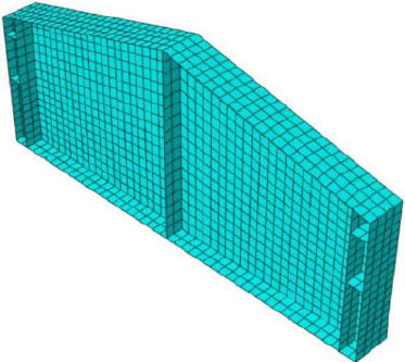
Finite element mesh configuration for flat web girder using S4R shell elements.
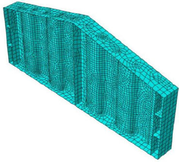
Finite element mesh for sinusoidal web girder showing discretization along wave profiles.
4.2. Material Constitutive Model
The steel material behavior was modeled using a bilinear stress–strain relationship with isotropic strain hardening. The elastic phase was defined by a Young's modulus of 200 GPa and a Poisson's ratio of 0.3, while the plastic phase incorporated a strain-hardening modulus of 5 GPa. The yield criterion followed the von Mises formulation with associated plastic flow. Yield stresses of 391 MPa and 425 MPa were assigned to the flange/stiffener plates and web plates, respectively, based on the coupon test results.
4.3. Boundary Conditions and Loading Protocol
The boundary conditions were applied to replicate the simply supported configuration used in the experimental tests.
Nodal constraints on shell edges: At the support locations (100 mm from each girder end, corresponding to a clear span of 1600 mm), translational restraints were applied to the nodes along the bottom flange width. At one support, translations in the vertical (Y), longitudinal (X), and transverse (Z) directions were restrained to simulate a pinned condition, while at the opposite support, only vertical (Y) and transverse (Z) translations were restrained, permitting longitudinal displacement to simulate a roller condition. Rotations about the transverse axis (Z) were left free at both supports to allow beam rotation.
Loading was applied using a displacement-controlled protocol, in which an incremental vertical displacement was imposed on the nodes along the top flange at mid-span, with a maximum applied displacement of 10 mm. Displacement control was selected to capture the post-peak softening response and to maintain numerical stability during the load-shedding phase after buckling.
4.4. Initial Geometric Imperfections and Analysis Procedure
To simulate realistic buckling initiation, initial geometric imperfections were introduced into all finite element models. The imperfection shape was derived from the first eigenmode obtained through a preliminary linear buckling analysis (eigenvalue extraction using the Lanczos solver in ABAQUS). The critical eigenmode, which corresponded to the dominant shear buckling mode of the web panel, was scaled and applied as an initial perturbation to the perfect geometry.
The imperfection amplitude was set to L/1000, where L is the total girder length (1800 mm), yielding an amplitude of 1.8 mm. This value is widely adopted in the literature for thin-web steel girders to approximate the combined effects of fabrication tolerances, welding distortions, and residual geometric deviations, as reported by Elgaaly and Seshadri [19]. An imperfection sensitivity study was carried out on TFW600 using amplitudes of L/500, L/1000, and L/2000, with L/1000 selected as it gave the closest agreement with the experimental results.
Residual stresses from welding were introduced as an initial stress field prior to loading, following the classical distribution for welded I-sections: longitudinal tensile residual stresses of 0.3fy were applied near the flange-to-web weld toes to simulate welding-induced thermal shrinkage, and longitudinal compressive residual stresses of 0.2fy were distributed across the web field. This distribution is consistent with the guidance in EN 1993-1-5 [20], Annex C, for initial imperfections and residual stresses in plated structures.
Following imperfection application, a geometrically and materially nonlinear analysis was performed using displacement-controlled loading, with vertical displacement applied incrementally at the loading point up to 10 mm in maximum increments of 0.1 mm. Large-deformation effects were accounted for by activating the NLGEOM (nonlinear geometry) option throughout. Convergence was handled using the default Newton–Raphson scheme in ABAQUS/Standard, with force and moment residual tolerances of 0.5%. To aid convergence in regions of negative tangent stiffness associated with buckling and post-buckling behaviour, automatic stabilisation was employed with a dissipated energy fraction of 0.0002. The load–displacement response was obtained by plotting the applied displacement against the sum of the support reactions, and the analysis was terminated once the load proportionality factor began declining steadily, indicating that post-peak behaviour had been reached.
5. VALIDATION OF THE FINITE ELEMENT MODELS
5.1. Ultimate Load Comparison
The ultimate loads predicted by the finite element models are compared with experimental results in Table 7 with errors within acceptable range. This close agreement confirms the reliability of the modeling approach for both flat-web and sinusoidal-web tapered girders.
| Specimens | Exp. Ultimate Load (kN) | FEA Ultimate Load (kN) | Error (%) |
|---|---|---|---|
| TFW400 | 270 | 280 | -4% |
| TFW600 | 433 | 412 | +5% |
| TFW800 | 620 | 599 | +4% |
| TSW400 | 405 | 400 | +1% |
| TSW600 | 620 | 630 | -2% |
| TSW800 | 703 | 690 | +2% |
5.2. Load–deflection Response
The initial elastic stiffness predicted by the FE models was within 99.5% of the experimental values for all specimens, confirming accurate representation of the boundary conditions and material elastic properties.
The load–deflection relationships obtained from both experimental and numerical analyses are presented in Figs. (17 and 18) for sinusoidal-web and flat-web girders, respectively. The curves demonstrate similar elastic stiffness, peak loads, and post-peak behaviors, confirming the robustness of the developed finite element models. Mid-span deflection showed accurate results, with errors within acceptable ranges, as shown in Table 8.
| Specimens | Exp. Deflection (mm) | FEA Deflection (mm) | Error (%) |
|---|---|---|---|
| TFW400 | 5.50 | 5.20 | +6% |
| TFW600 | 5.98 | 5.78 | +3% |
| TFW800 | 7.28 | 7.25 | +1% |
| TSW400 | 6.00 | 5.80 | +3% |
| TSW600 | 6.51 | 6.75 | -4% |
| TSW800 | 8.78 | 9.00 | -3% |
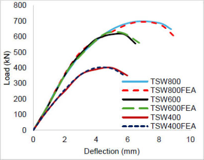
Comparison of the load-midspan deflection relationships, experimental and finite elements of tapered sinusoidal-web girder.
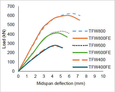
Comparison of the load-midspan deflection relationships, experimental and finite elements of tapered flat web girder.
6. LIMITATIONS AND SCOPE
The present study has limitations that should be considered when interpreting its findings. All sinusoidal-web specimens shared the same corrugation geometry (71 mm depth, 341 mm wavelength). Furthermore, only one specimen was fabricated and tested per configuration; however, the close agreement between the experimental results and the validated finite element models provides confidence in the reported findings. The girder span was limited to 1800 mm under static monotonic loading, and the findings may not extend directly to longer spans without further verification. Finally, the finite element models were used solely for experimental validation and were not extended to a broader parametric study. Formal statistical analysis was not applicable due to the use of one specimen per configuration. The use of a single sinusoidal web geometry is also acknowledged as a limitation and is recommended for future parametric studies. These constraints establish the limitations within which the reported findings and design implications should be applied.
CONCLUSION
This study presented the first experimental and numerical investigation of tapered steel I-girders with sinusoidal corrugated webs under three-point loading, comparing their performance against flat-web counterparts at mid-span depths of 400, 600, and 800 mm. Sinusoidal-web girders consistently outperformed flat-web girders in ultimate load capacity, with improvements of 50%, 43%, and 13% for the three configurations, respectively. Flat-web girders failed through localised diagonal shear buckling, while sinusoidal-web girders developed distributed or global buckling modes with stable tension field action across multiple corrugation folds, resulting in a markedly more ductile response. This was reflected in web strain measurements, where sinusoidal-web specimens sustained 9% to 46% higher peak strains than their flat-web counterparts, and in energy absorption capacity, with TSW800 absorbing approximately 1.4 times the energy of TFW800. Nonlinear finite element models reproduced the experimental ultimate loads and mid-span deflections with average discrepancies of 3% and 3.3%, respectively, and captured the contrasting stress distribution patterns between the two web types, confirming the reliability of the modelling approach.
The Nikoomanesh–Goudarzi formula gave acceptable predictions for the 400 and 600 mm specimens but overestimated the capacity at 800 mm depth by 10%, while EN 1993-1-5 was conservative across all specimens, with Pexp/PEN ratios between 1.80 and 2.05, indicating that prismatic analytical models are not directly applicable to tapered configurations and that dedicated design provisions are required.
A significant finding is the dependence of sinusoidal-web strength capacity on the corrugation-to-depth ratio. At 400 mm depth, a 50% load capacity improvement was observed relative to the flat-web girder counterpart. At 800 mm, the improvement fell to 13%. This reflects the shift from local to global buckling as web slenderness increases, which means that the fixed corrugation geometry was insufficient to anchor effective tension fields. This has direct implications for design practice: neither AISC 360-22 nor EN 1993-1-5 currently addresses corrugated-web tapered girders. Extending the current code equations to include corrugation geometry parameters, similar to the accordion-effect coefficient suggested by Huang et al. [15], is one solution for tapered configurations.
AUTHORS’ CONTRIBUTIONS
The authors confirm contribution to the paper as follows: G.G.J.: Contributed to experimental setup, data collection, and finite element modeling; B.S.A.: Conceived the research idea, supervised the experimental program, performed data analysis, and drafted the manuscript; W.S.A.: Contributed to data analysis, prepared all figures and tables, and reviewed the manuscript. All authors reviewed the results and approved the final version of the manuscript.
LIST OF ABBREVIATIONS
| ABAQUS | = Finite Element Analysis Software |
| AISC | = American Institute of Steel Construction |
| CEN | = European Committee for Standardization |
| EN | = European Norm |
| FEA | = Finite Element Analysis |
| SCW | = Sinusoidal Corrugated Web |
| TFW | = Tapered Flat Web girder |
| TSW | = Tapered Sinusoidal Web girder |
AVAILABILITY OF DATA AND MATERIALS
The data that support the findings of this study are available from the corresponding author upon reasonable request.
ACKNOWLEDGEMENTS
The authors would like to acknowledge the College of Civil Engineering, University of Technology, Baghdad, Iraq, for providing the laboratory facilities used in this study.